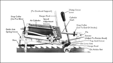
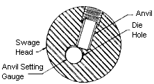
| Setting
Head to Tooth 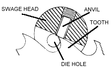
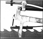
- Set swage on saw. Run saw through slot in swage head
and rest shoe on saw tips. Remove die from die hole and look to see if flat end of
anvil is sitting flat on tooth with no light at either front or back of anvil.
- To adjust, loosen two screws holding guide arm and rotate
head forward or backward until anvil sets flat on back clearance of tooth.
- Tighten screws in guide arm. Recheck.
Setting Die Lever to End of Stroke
 |
1. Assemble die holder, handle and die
holder nut snugly.
2. Insert into die hole and rotate lever counter-clockwise until eccentric
die contacts anvil. |
3. Slip die lever on die
holder until a comfortable swaging position is reached.
4. Remove lever and die assembly. Tighten nut on die holder. Then
replace in die hole. Mark die lever to correspond with split in die holder for ease
of re-establishing setting and as a reference if die holder should slip in lever.
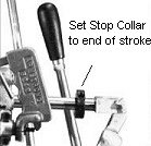
5. Move die lever forward until eccentric die contacts anvil.
6. Move die lever back slightly (about 1/16"). Set front stop by
bringing it up against the die lever and tighten.
7. It is important to set front stop to hold eccentric die away from face of
anvil to avoid damage to die or anvil. |
|
Set Front
Guide Arm Spring Screw
|
1. Set gap between end of the screw and
guide arm spring if it is desired to pull the tooth point down.
2. Pulling point down will permit heavier grinding on back of tooth, if
necessary to maintain tooth shape. |
Setting Stop Collar For Bite
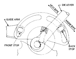
- Set swage on saw and line up eccentric part of die by eye so
it will pick up about 1/8" or 3/16" of tooth.
- Set stop collar (farthest from swage head) by sliding it back
and forth along the cylinder shaft. Toward cylinder reduces bite, away from cylinder
increases bite.
- Swage tooth.
- Adjust stop for more or less bite.
WARNING: Avoid contact
with the air cylinder shaft when air supply is connected to swage. You are working
in a dangerous environment. To minimize risk of injury, keep your work area clean
and all tools in good working condition. |
Additional
Recommendations for Air Swages
 |
1. Use 1/4" air hose. We
recommend 80 lbs. maximum and 60 lbs. minimum.
2. Use an air regulator and gauge to control pressure, in addition to the |
usual shut-off valve in the air
line. This allows precise control of the air pressure. The regulator and gauge
should be placed in the air line near swage operation, but not attached to the swage.
3. The piston in the air cylinder is fastened to the piston rod with a
shearing pin. In the event of an accident or excessive air pressure, the pin shears
off, releasing the piston and preventing possible damage to parts.
4. Armstrong has air valve repair kits available (Part No. 5352-R) or you can
send air valves directly to Armstrong for repair.
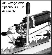
5. Armstrong manufactures an optional air trigger conversion kit or
"trip assembly". Refer to photo. (Part No. 6276-C1)
6. Speed of cylinder stroke can be controlled by two screws located on the
valve (see front photo) - one for each direction. Note: Swaging too quickly can
cause tooth crumble. Keep your stroke smooth and steady. |
DIE SELECTIONS: |
| Long |
The long bite die is the mildest
die, and produces the smallest kerf. |
| Short |
The short bite die is the most
frequently used for "average" conditions. |
| Extra Short |
The extra short die is the most
aggressive, giving the heaviest kerf. |
|
Maintenance Armstrong Air Swages require very little
maintenance. Regular cleaning is the key to keeping a good, accurate, reliable tool.
Swages have a number of parts that are consumed during swaging and need to be
replaced. Don't wait until you are having difficulties to replace them.
- Keep spare parts on hand and use carbide whenever
possible. Carbide lasts longer, works better and costs less in the long run.
- Keep swage valve and cylinder well lubricated using the
lubricator supplied with each swage or you may wish to use an in-line oiler attached to
your air source.
- Make sure only clean, filtered air is directed into the swage
cylinder.
- Wipe swage down and inspect for loose parts and wear at least
once a week. When the die shows signs of wear, move it over 1/4" minimum.
- Refer to Armstrong's "Back to the Basics" Swage and Shaper
Troubleshooting Guide for more detailed information and answers to many commonly asked
questions.
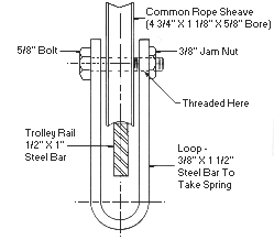
Suggested Overhead
Support Method
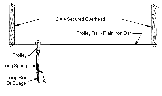
Place Trolley rail high enough so not to
interfere with handling saws (approximately 7 feet). To lift swage up and out of the
way when not in use, arrange a small rope and sheave from higher up with end of line and
attach to swage loop "A". |