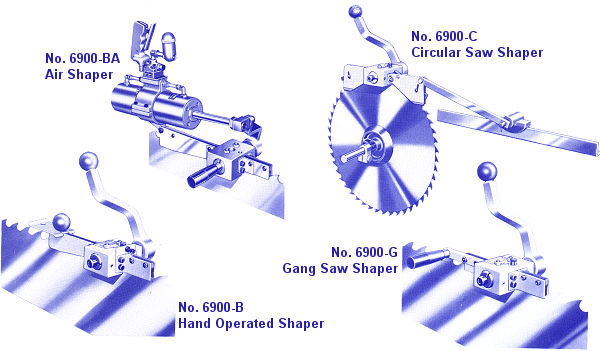
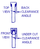
ADJUSTMENT FOR WIDTH OF POINT
|
The side dies are factory ground to your specifications.
The dies are ground so that they will produce the desired kerf, or
width of finished point can be increased as needed up to the following amounts:
- With dies ground to 2� back clearance: .005"
- With dies ground to 4� back clearance: .010"
- With dies ground to 8� back clearance: .020"
Standard back clearance unless otherwise specified is 8� , the same amount provided with an older model Armstrong shapers.

MANUFACTURING COMPANY
5504 S 11th St, Ridgefield, WA 98642 USA
(503) 228-8381 Fax: (503) 228-8384
www.armstrongblue.com
|
Suggestions
on the Adjustment and use of
6900 Series Armstrong Shapers for Band, Gang or Circular Saws |
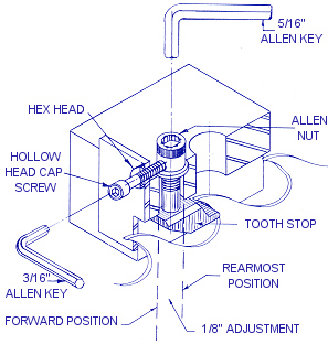
CENTERING THE SIDE DIES AND LOCATING THE HANDLE
- Release the large knurled bushing by loosening the spanner locknut with the spanner
wrench.
- Hold the operating handle above the shaper in a vertical position, adjust the right hand
side die by turning the knurled bushing clockwise so that the side die contacts the saw
plate in approximately the center of the observation hole in the top of the shaper head.
- With the operating handle still in the vertical position, adjust the left hand side die
by turning the hollow head cap screw into the shaper head until the side die contacts the
saw plate. Using the 3/8" allen key.
- Adjust the operating handle to a suitable working position by adjusting the hollow head
cap screw outward from the shaper head to lower the handle or into the head to raise the
handle.
- With the adjustments complete, tighten the spanner locknut with the spanner wrench.
|
SHAPING MORE THAN ONE THICKNESS OF SAW
Because the clearances are ground into the dies, and the fact that the clearance of the
finished point is always in relation to the thickness of the plate, the 1/8" movement
of the tooth stop often makes it possible to use the shaper on more than one thickness of
saw without changing side dies.
SWAGING FOR PROPER TOOTH POINT
The No. 6900 shapers are designed for maximum uniformity, and the saw itself acts as the
stop for the side dies. As a result, it is important to swage the saw to the proper
amount. Generally this will be less than is common with older type shapers.
This has the advantage of producing less work hardening, and less
crumbling of the tooth point.
In some instances the corner produced on the tooth point may not be as
heavy as with the older swaging and shaping procedure. Any reduction in corner, however,
is more than out-weighted by the accuracy and precision provided by the No. 6900 shaper,
and not sufficient to cause a problem.
EFFECTS OF IMPROPER SWAGING
Swaging the tooth point too wide or too narrow will have the following effects:
- Too wide a point provides more than enough material to produce the tooth point, as
called for by the clearances ground into the side dies. The result is an upward bulge on
the tooth, and the width of point should be reduced.
- Swaging too thing a point can also cause an upward bulge or bend on the tooth point. In
this case the bend upward is the result of too little material. To correct this condition,
leave the cutting edge area of the point thicker by rolling the swage die back, or
stopping the action of the swage die just a little ahead of the anvil.
|
| SIDE
DIE AND TOOTH STOP SELECTOR |
| To calculate side
clearance: |
Shallow Tooth Range |
Deep Tooth Range |
| Saw Kerf |
.125 |
16 gauge saws and thinner |
15 gauge saws and heavier |
| 16 gauge saw |
(-).065 |
11/16" deep and shallower: |
�" deep and deeper: |
2.060 |
6982 side dies |
6980 side dies |
| Clearance per side |
.030 |
6983 tooth stop |
6981 tooth stop |
|
Suggestions
on the Adjustment and use of
6900 Series Armstrong Shapers for Band, Gang or Circular Saws |
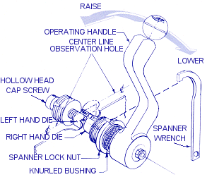
| NOS.
6900-B, 6900-G, & 6900-BA BAND, GANG, & BAND-AIR SHAPER ALIGNMENT |
 |
The Band, Gang, and Air
Operated No. 6900 Shapers all require the wear shoes to be in line |
with
the bottom of the slot in the shaper head. A straight edge should be used to insure proper
alignment of both wear shoes to the shaper head. |
OPERATING INSRUCTIONS FOR NO. 6900-BA ARMSTRONG AIR
DRIVEN SHAPER
- �" air hose is used (same as at service stations).
- Suggested operating air pressure: 80 lbs. maximum. 60 lbs. minimum.
- We suggested the use of an air regulator and gauge to control the pressure, in addition
to the usual shut-off valve in the air line – the reason being that it is not
possible to control the pressure with the shut-off valve, as it merely restricts the flow
and the pressure remains the same.
- Regulator and gauge should be placed in the air line near the operation, but not
attached to the shaper due to the weight.
- Use of the lubricator supplied with each shaper is recommended to keep the valve and
cylinder well lubricated.
- Speed of cylinder stroke can be controlled by two screws located on the side of the
valve directly below the operator’s finger tips when the hand is on the valve handle
and trigger.
- Shaper adjustments are the same as those required on an Armstrong No. 6900 hand shaper.
LUBRICATION
All units are lubricated at the factory. The moving parts (side die and clamp screw) will
need lubrication with either oil or "Lubriplate" grease as necessary to reduce
wear. |
SIDE DIE GRINDING NOMENCLATURE |
 |
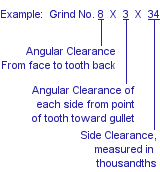 |
INFORMATION FOR ORDERING
The following specifications are needed to adapt your new shaper to
your exact requirements:
- Thickness of the saw.
- Width of the finished point.
- Standard back and side clearances are 8 degrees x 3 degrees, and will be furnished
unless otherwise specified.
| NO.
6900-C CIRCULAR SAW SHAPER ALIGNMENT |
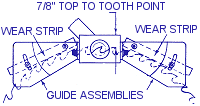 |
This Shaper is operated in
the same manner as the other 6900 series except for the two following adjustments: |
- Adjust the wear strips to contact two teeth on each side
near Shaper head.
- Adjust guide assemblies up or down so tooth point is
7/8" below top of head. Both assemblies should be at the same height.
|
MANUFACTURING COMPANY
5504 S 11th St, Ridgefield, WA 98642 USA
(503) 228-8381 Fax: (503) 228-8384
www.armstrongblue.com |
|
|