- Both the feed and wheel cams have a timing hole (marked with a "T") and a slash on their side at the rim. Older style cast iron cams had only a raised timing mark that was painted yellow.
- After bolting the cams together on the cam shaft, revolve the cams on the shaft until the timing hole (or mark) is on the horizontal center line through the cam shaft, parallel to the floor.
- Place a rod (a piece of welding rod usually works well for this) through the timing hole on both cams. Adjust the cams until the rod is parallel to the cam shaft. When timing cast iron cams, use a stick to confirm that the center of the cam shaft and the two timing marks are the same distance off the floor ... and therefore parallel to the floor.
- The timing marks must line up and the cams must be rotating in the direction of the arrows on the cams to make the tooth shape the cams are designed to produce.
Fine Tuning Band Saw Cams
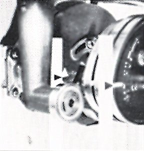
A simple method for fine tuning the timing of the cams works best with two people: one behind the machine turning the fan on the electric motor and one in front of the machine confirming that grinding wheel begins to lift about .002" (.05 mm) before the feed finger begins to advance the saw.
- Disconnect and "lock out" the electrical power to the machine.
- Adjust the saw to the normal grinding position.
- Remove the fan cover from the motor that drives the cam shaft. Turn the motor fan manually (a small piece of UHMW works well), which will turn the cam shaft very slowly. (Caution: the fan must be rotated in the correct direction! The cam shaft turns so that the cam shaft shift lever is being forced down into the "notches").
- Adjust the sharpener so that the feed finger is in the fully retracted position and the grinding wheel is in the bottom of gullet. Both cam followers must be in contact with the cams.
- Adjust the wheel lift screw so that the grinding wheel just begins to contact the bottom of the gullet. You should still be able to rotate the wheel by hand, but you will hear the wheel slightly scraping the bottom of the gullet while the wheel is being turned. (Note: most grinding wheels that have been dressed by hand will be slightly out-of-round. It is not unusual that the wheel will only be in contact with the bottom of the gullet for just a small portion of the entire 360 degree periphery.)
- Continuously check that the grinding wheel has maintained contact with the bottom of the gullet by slowly "rocking" the wheel by hand and listening for the light scraping sound of the wheel in the bottom of the gullet as the feed finger advances closer to the face of the next tooth.
- The wheel should lift about .002" to .005" (.05 - .125 mm) before the feed finger begins to advance the saw. The lifting of the wheel will be imperceptible. But you will hear that the wheel has risen because the scraping of the wheel on the gullet will stop.
It is a good practice to check the cone screws in both the rocker head (there are four of them) and the feed finger arm (there are two of them here) before attempting to time cams. The wheel lift pivot nut should also be inspected. All of these parts should be replaced if there is significant wear. Changing these parts may alter the cam timing of the cams.
- Place the wheel cam for the deepest tooth in the No. 1 position, against the wheel cam hub.
- Place the wheel cam for the next deepest tooth in the No. 2 position, against cam No. 1.
- Place the wheel cam for the shallowest tooth in the No. 3 position, against wheel cam No. 2.
- Keep all feed cams paired in the same rotation. (See illustration.)
| SPACE | DEPTH |
|
|
||
| In. | mm | In. | mm | ||
| 1 | 25.40 | 1/4 | 6.4 | 66F | BW |
| 1 | 25.40 | 5/16 | 7.9 | 72A | BA |
| 1 1/4 | 31.75 | 5/16 | 7.9 | 45E | BX |
| 1 1/4 | 31.75 | 3/8 | 9.5 | 73A | BB |
| 1 1/2 | 38.10 | 3/8 | 9.5 | 4B | BC |
| 1 1/2 | 38.10 | 7/16 | 11.1 | 56A | BE |
| 1 1/2 | 38.10 | 1/2 | 12.7 | 74A | BU |
| 1 1/2 | 38.10 | 5/8 | 15.9 | 90A | BF |
| 1 3/4 | 44.45 | 1/2 | 12.7 | 41A | BD |
| 1 3/4 | 44.45 | 5/8 | 15.9 | 42A | BG |
| 1 3/4 | 44.45 | 11/16 | 17.5 | 45F | BJ |
| 1 3/4 | 44.45 | 3/4 | 19.1 | 50E | BH |
| 1 3/4 | 44.45 | 7/8 | 22.2 | E | BK |
| 2 | 50.80 | 3/4 | 19.1 | 65A | BI |
| 2 | 50.80 | 7/8 | 22.2 | 57A | BN |
| 2 | 50.80 | 1 | 25.4 | 54A | BL |
| 2 1/4 | 57.15 | 1 1/8 | 28.6 | 98A | BT |
| 2 1/2 | 63.50 | 1 1/16 | 27.0 | 36A | BM |
| 2 1/2 | 63.50 | 1 1/4 | 31.80 | 43A | BR |
| 2 3/4 | 69.85 | 1 15/16 | 33.3 | 44A | BZ |
| 3 | 76.20 | 1 15/16 | 33.3 | 38A | BP |
| 3 | 76.20 | 1 3/8 | 34.9 | 89A | BQ |
- Is the tooth being produced like the tooth drawing supplied with the cams?
- Are part numbers on cams same as specified on tooth drawing?
- Cams running in proper direction? Cams turn so as to force handle end of shift lever into notches in shift lever support.
- Cam follower bearing must ride cam for full revolution of cam and does not hold up by nut on depth stop rod or other obstruction.
- Timing marks on both cams must match.
- Grinding wheel thickness as specified by drawing.
- Thicker grinding wheel will make a larger throat and a shallower tooth. (Thicker wheel may be used if dressed to proper thickness.)
- Thinner grinding wheel will make a smaller throat and deeper tooth.
- Make sure head is adjusted to produce the hook angle as specified on the tooth drawing.
- More hook will give shallower tooth.
- Less hook will give deeper tooth.