| Previous Page | Table of Contents | Next Page |
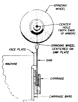
ALIGN CENTER OF SAW TO CENTER OF GRINDING WHEEL ARBOR

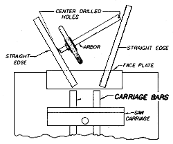
1. Holding a straight edge on the face plate, check the alignment of the grinding wheel arbor front and back while the grinding head is fully lowered and again, front and back, when the head is raised. (See our Arbor Alignment System)

2. Adjust the arbor to the faceplate without disturbing the relationship of the faceplate to the feed finger arm.
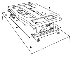
3. Adjust the arbor by loosening the cap screws that bolt the cast iron bases for the links to the top of the sharpener frame. The boltholes are elongated, allowing the bases to move as needed. Adjust one base at a time.

4. The graduated circle bases and links must be aligned so they are the exact same distance apart, top and bottom, front and back, with the links perpendicular.
Since 1980, NEW LONGER LINKS (Part No. 461), for the Nos. 4 and 4-21/22 sharpeners have allowed additional wear on the grinding wheel while maintaining the hook and tooth shape. The 3/4" longer links are completely interchangeable with old-style, Part No.341.
| Previous Page | Table of Contents | Next Page |