| Armstrong Operating Instructions: |
 |
| DESCRIPTION
Using
the Armstrong Tension Gauge Grinder eliminates use of worn-out, inaccurate gauges and
allows for uniform, freshly ground gauges to be made on-the-spot. Having a tension gauge
grinder in the filing room, saves the expense of sending gauges out for regrind and avoids
time delay.
Developed from a design provided by Jim Reid, head filer at the Pope and Talbot mill in Washington, both convex and concave tension gauges can be ground quickly and precisely. The easily adjusted grinder requires no template or master for grinding band saw gauges. Although, not specifically designed for grinding RPM gauges used on circular saws, the tension gauge grinder has been used for these gauges as well. A 900 RPM gauge is approximately a 125 ft. circle. A slightly larger circle gauge is normally used for slower RPMs. |
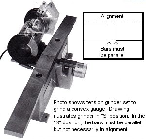
SET UP Completely assembled, the tension gauge grinder needs only to be bolted down to a sturdy work surface and plugged in. Electrical requirement: 115 volts (4 amps). Transformer for 240 volt, 50 Hz power is available. Before beginning, set knurled handwheel to the "S" (straight edge) position. Check to see that steel rails are parallel to each other. If not, adjust the handwheel. Use a 24" straight edge to make sure bars are parallel. Then, with a 5/32" Allen wrench, loosen set screw on the knurled handwheel and move the handwheel to align "S" mark with indicator mark. Secure set screw and recheck. (Refer to photo on reverse side.)
|

| Armstrong
Operating Instructions: Tension Gauge and Straight Edge Grinder |
|||||||||||||||||||||||||||||||||||||
| TWO SIMPLE SETTINGS
For example, starting with handwheel at "S", turn clockwise to select for concave (hollow) gauge. ("H" on handwheel refers to Hollow.) When grinding convex gauges, turn wheel counter-clockwise past selected setting. Stop and turn the wheel clockwise back to correct setting. Setting is always made turning the handwheel clockwise. 2) Smaller, blue handwheel positions grinding wheel. Turning clockwise moves wheel out; counter- clockwise brings wheel in. This allows very fine control of finishing grinding passes - the key to accurate gauges. Check the cam follower bearings regularly. If they are loose and move side to side, this indicates wear and a need for replacement. Watch for wear on the steel rails and replace as necessary.
|
PREPARING GAUGE
|
||||||||||||||||||||||||||||||||||||
| Armstrong
Operating Instructions: Tension Gauge and Straight Edge Grinder |
|||||||||||||||||||||||||||||||||||||
| WHAT IF?
WHAT IF THE PIVOTING STEEL RAILS ARE PARALLEL TO EACH OTHER, BUT THEY DO NOT LINE UP STRAIGHT? No problem. For accurate grinding, the bars must be parallel to each other in the straight edge ("S") position, but they do not have to be in perfect alignment. WHAT IF I GRIND TWO GAUGES WITH THE SAME SETTINGS, BUT THEY ARE NOT IDENTICAL?
Not turning the wheel in the same direction and grinding too quickly are the two most frequent causes of non-uniform gauges. WHAT IF THE KNURLED HANDWHEEL GETS STUCK WHEN I TRY TO SET IT? If the handwheel stops before it reaches the setting you need, loosen the knurled handwheel covering with an Allen wrench and remove it. Next loosen set screw on the steel sleeve underneath and pull sleeve out approximately 1/8". Retighten set screw and replace handwheel covering. CAUTION: INJURY TO THE OPERATOR AND/OR DAMAGE AND/OR SAFETY INSTRUCTIONS ARE NOT FOLLOWED. |
GRINDING
ON/OFF switch is located on front of motor. With gauge lightly touching grinding wheel on one edge, move carriage back and forth SLOWLY. Maintain a firm, even pressure on carriage. Cam follower bearings should be in contact with steel rails at all times. Turn small handwheel counter-clockwise. Bring grinding wheel in until there is light sparking. (Spark will not be consistent all the way across the gauge until you are finished.) When the spark has diminished, re-adjust grinding wheel down a fraction of a turn (approximately 20 degrees) until you get light sparking again. Repeat process until gauge is completely ground and edge is smooth and even. Grinding too quickly causes heat build-up, distorting accuracy of gauge. Allow gauge to cool to room temperature before making final light "spark- out" grind. For new gauges, allow approx. 30 min. Per side. Regrinding, approx. 10 min WARNING: EYE PROTECTION MUST BE WORN WHEN OPERATING THIS MACHINE. UNDER NO CIRCUMSTANCES OPERATE MACHINE UNLESS ALL SAFETY GUARDS ARE IN PLACE. FAILURE TO FOLLOW ALL INSTRUCTIONS MAY RESULT IN PERSONAL INJURY AND/OR DAMAGE TO THE MACHINE.
|
||||||||||||||||||||||||||||||||||||